
Choosing the best Switch Terminal is rarely a matter of selecting the lowest quoted price. Global buyers must match terminal design with voltage, current, wiring method, enclosure space, and operating environment. A compact terminal may fit a crowded control panel, yet its screw access could be poor during field maintenance. Small details matter.
This guide examines practical selection factors from a procurement and engineering perspective. It considers conductive materials, insulation quality, pitch, clamping force, temperature tolerance, vibration resistance, and expected service life. It also discusses recognized testing requirements, supplier documentation, traceability, and market-specific certification expectations. Requirements can differ between industrial equipment, renewable energy systems, transportation controls, and building automation. Buyers should confirm current standards with qualified professionals before approval.
Real purchasing decisions involve compromise. A terminal with excellent electrical performance may have longer lead times. A cheaper model may create hidden labor costs through difficult installation or repeated retightening. I have seen specifications appear complete while omitting wire-size ranges and torque values. That gap can delay an entire production batch. Not every supplier communicates clearly.
The most reliable approach combines verified technical data, sample testing, and supplier assessment. Buyers should request drawings, material declarations, inspection records, and clear warranty terms. A sample should be checked with the actual wire, tool, and enclosure planned for production. It may reveal an unexpected fit problem. This article provides a structured way to compare options without assuming one Switch Terminal suits every global application. The final decision should balance safety, performance, availability, documentation, and total ownership cost.
What Is the Best Switch Terminal for Global Buyers?
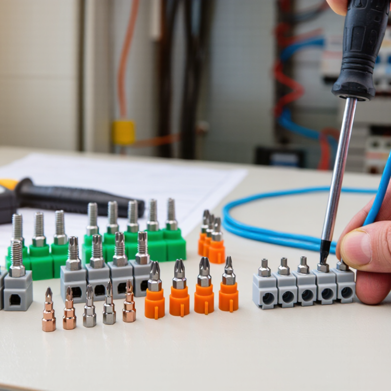
A switch terminal is the conductive connection point between a switch and an external circuit. It carries current through solder, screw, quick-connect, PCB, or wire-lead connections. Each type fits a different installation. Solder terminals suit compact assemblies, while screw terminals allow easier field maintenance. Quick-connect terminals save assembly time, but their crimp quality matters. I have seen loose crimps create heat marks after repeated switching. That detail is easy to overlook.
Poles describe how many separate circuits a switch controls. A single-pole switch controls one circuit, while a double-pole switch controls two. Throw describes the available circuit paths, such as on-off or changeover. Common configurations include SPST, SPDT, DPST, and DPDT. Pitch means the center-to-center distance between adjacent terminals, especially on PCB-mounted switches. A mismatch of only one millimeter can prevent proper installation. Measure the board footprint, not just the product drawing.
Rated current shows how much current the terminal can safely carry under stated conditions. Check the rated voltage, load type, switching frequency, wire size, and operating temperature together. Inductive loads can stress contacts more than simple resistive loads. For global purchasing, request complete datasheets, dimensional drawings, sample testing, and applicable conformity documents. Specifications are not always interpreted consistently. Rechecking them may feel slow, but it prevents costly redesigns.
What Is the Best Switch Terminal for Global Buyers?
For global buyers, the best switch terminal is not simply the smallest or cheapest option. It must match the application, wiring method, voltage, current, and installation environment. IEC 60947-7-1 is important for terminal blocks used in low-voltage switchgear and controlgear. It addresses construction, electrical performance, temperature rise, and verification requirements. A terminal that passes one test may still need additional evaluation for another market.
UL 1059 provides a different compliance reference for terminal blocks used in North American applications. Buyers should check the exact spacing, wire range, insulation rating, and field-wiring conditions. Do not rely on a familiar logo alone. Request the current test report, certificate details, and product marking requirements. Small details matter. A 2.5 mm² conductor, for example, may require a different clamping design than a 10 mm² conductor.
RoHS supports material compliance by restricting specific hazardous substances in electrical products. CE marking shows conformity with applicable European Union requirements, but it is not a universal quality certificate. The manufacturer should provide a Declaration of Conformity and identify the relevant directives or regulations. In practice, documentation is often the weak point. A technically sound terminal can still face delays when files are incomplete, outdated, or inconsistent. Buyers should also inspect torque markings, flame resistance data, and sample performance before approving large quantities. The process is not flawless, and assumptions deserve a second review.
| Terminal Format | Typical Construction | Common Advantages | IEC 60947-7-1 Considerations | UL 1059 Considerations | RoHS and CE Documentation | Best-Fit Applications | Global Buyer Verification |
|---|---|---|---|---|---|---|---|
| Feed-Through Screw Terminal | Copper-alloy current bar, insulating thermoplastic housing, and a screw-clamp conductor connection. | Simple installation, broad conductor compatibility, and easy visual inspection. | Confirm the declared rated voltage, rated current, conductor size range, temperature rise, insulation properties, and tightening torque. | Request the applicable UL 1059 recognition or listing information, including the terminal-block category, wire range, voltage, current, and field-wiring conditions. | Obtain a current RoHS declaration for restricted substances and an EU Declaration of Conformity when CE marking is applicable to the complete equipment. | Control cabinets, switchgear, industrial machinery, power distribution, and equipment wiring. | Check markings on the terminal, test reports, torque specifications, conductor compatibility, and complete assembly ratings. |
| Spring-Clamp Terminal | Spring steel clamping element combined with a copper-alloy current path and flame-retardant insulating housing. | Resists loosening caused by vibration and generally reduces maintenance associated with retightening. | Verify tests for electrical performance, mechanical retention, conductor insertion, temperature rise, and compatibility with solid, stranded, or ferruled conductors. | Confirm whether the certified configuration permits the intended wire type, wire size, insulation temperature, and installation method. | RoHS status depends on the materials used. CE documentation should identify the applicable EU legislation for the finished product rather than treating CE as a standalone product certificate. | Vibration-prone machinery, factory automation, transportation equipment, and compact control panels. | Verify the required insertion tool, strip length, permissible conductor types, pull-out performance, and maintenance instructions. |
| Barrier Screw Terminal | Individual screw terminals separated by insulating barriers, often with a pressure plate or clamp system. | Provides clear circuit separation and can be suitable for higher-voltage or multi-circuit wiring layouts. | Confirm creepage distance, clearance, dielectric strength, rated voltage, rated current, and the permitted conductor termination method. | Check the UL 1059 file information for spacing, field-wiring suitability, wire range, and any restrictions on adjacent circuits. | Request the material declaration and RoHS evidence for housing, screws, barriers, plating, and any accessories. CE assessment remains dependent on the final equipment. | Power supplies, motor controls, industrial panels, HVAC equipment, and equipment requiring circuit segregation. | Compare the terminal spacing with the system voltage and pollution environment; verify torque and short-circuit requirements. |
| Protective-Earth Terminal | Metal current path with a green-and-yellow identification feature and a housing or mounting system designed for protective bonding. | Supports reliable protective-earth continuity and clear identification during installation and maintenance. | Confirm protective-circuit continuity, resistance, mechanical strength, corrosion protection, marking, and compatibility with the mounting rail or panel. | Verify the applicable grounding-terminal requirements, recognized configuration, conductor range, and permissible mounting method under the relevant UL file. | Check RoHS evidence for metal plating and insulation materials. CE compliance should be documented as part of the complete electrical equipment risk and conformity assessment. | Control cabinets, machine frames, distribution boards, and equipment requiring protective bonding. | Confirm green-and-yellow identification, earth continuity test results, mounting integrity, and compatibility with the protective conductor system. |
| Multi-Level Terminal | Two or more electrically separate terminal levels integrated into one insulating housing. | Saves panel space and increases wiring density while maintaining separate circuits. | Check level-to-level and terminal-to-terminal clearances, insulation system, rated current for each level, heat dissipation, and accessibility. | Verify that the UL 1059 certification covers the exact number of levels, conductor arrangement, wire range, voltage, and current combination. | Request a bill-of-materials-based RoHS declaration. CE documentation should cover the completed equipment and any relevant low-voltage or EMC requirements. | Compact control cabinets, automation systems, instrumentation, and high-density signal distribution. | Review derating data, test access, screwdriver clearance, jumper compatibility, labeling space, and thermal performance. |
| Disconnect or Fuse Terminal | Terminal block with a disconnect link, test point, fuse holder, or removable circuit-protection element. | Allows circuit isolation, testing, or localized overcurrent protection within the terminal assembly. | Verify the ratings of the complete configuration, including the disconnect mechanism, fuse type, touch protection, temperature rise, and short-circuit performance. | Confirm UL 1059 coverage for the exact fuse or disconnect arrangement, including fuse dimensions, voltage, current, wire range, and access conditions. | Check RoHS status of the terminal and replaceable components. CE conformity must also consider the protection function and the finished equipment design. | Measurement circuits, process control, safety-related isolation, instrumentation, and maintenance-friendly panels. | Verify fuse compatibility, replacement access, finger-safe protection, labeling, spare-part availability, and fault-current requirements. |
What Is the Best Switch Terminal for Global Buyers?
Copper and aluminum behave differently at the same temperature. The International Annealed Copper Standard, referenced by ASTM B193, assigns copper 100% IACS conductivity, about 58 MS/m at 20°C. Aluminum reaches roughly 61% IACS, or 35 MS/m. This difference means an aluminum conductor needs a larger cross-sectional area for similar resistance. Lower conductivity can also increase voltage drop and heat at a poorly prepared terminal.
Copper usually offers stable crimping, strong mechanical performance, and easier installation. Aluminum can reduce weight and material cost, but it needs careful engineering. Its oxide layer is electrically resistant. Thermal expansion can also loosen an unsuitable connection. IEC 61238-1 testing highlights the importance of electrical stability during heating cycles. Field failures are not always caused by the metal itself. Incorrect torque, mixed metals, moisture, and undersized terminals often matter more. The conductivity figures are clear. The final choice is not.
Tips: Match the terminal to the conductor material and size. Check the manufacturer’s torque value with a calibrated tool. For aluminum, use terminals specifically rated for aluminum and follow the required surface preparation. Avoid assuming a copper terminal is automatically suitable. ASTM B193 measures resistivity, not complete switch performance. This distinction is easy to miss. Before international purchasing, request test records, temperature-rise data, and certification for the intended installation environment.
At 20°C, copper has an electrical conductivity of approximately 58 MS/m, while aluminum measures approximately 35 MS/m. Higher conductivity generally means lower electrical resistance for the same conductor size and length.
What Is the Best Switch Terminal for Global Buyers?
Safety begins with the terminal’s IP code, not its appearance. An IP65 rating indicates dust protection and resistance to water jets. However, it does not guarantee safe immersion or every installation condition. Buyers should check the complete code, test method, mounting position, and sealing details. A small gap around a cable gland can defeat an otherwise strong enclosure.
Temperature rise deserves equal attention. High current creates heat at contact points, especially when terminals are loose, contaminated, or poorly crimped. Review the rated current, conductor size, ambient temperature, and duty cycle together. A terminal may pass laboratory testing yet perform differently inside a crowded cabinet. I have seen specifications look reassuring until ventilation and tightening torque were examined. That experience still makes me cautious.
Tips: Ask for temperature-rise data at the intended current. Confirm the 1,000-V rating covers working voltage, insulation, clearance, and creepage. Check whether the rating applies to AC, DC, or both. Request independent test reports and installation instructions. Do not treat 1,000 V as a complete safety promise. Regional certification requirements may also differ, so technical documents should be reviewed by a qualified engineer. Small details matter.
A reliable switch terminal starts with the electrical load, not the catalog price. Check the continuous current and inrush current separately. A motor may briefly demand several times its running current. Choose a terminal with a safe margin, then review its temperature derating. Voltage rating also matters. Insulation, spacing, and contact design should match the intended AC or DC circuit.
Wiring details often decide whether installation is smooth or frustrating. Confirm the accepted wire range, conductor type, strip length, and tightening method. Screw, spring, and crimp connections each suit different production conditions. Global projects may use different wire gauges, tools, and installation habits. I have seen a technically suitable terminal fail because the cable did not fit the entry opening. The datasheet was correct. The selection process was incomplete.
Environment can change the ranking quickly. In a humid cabinet, choose suitable sealing, corrosion resistance, and insulation materials. For outdoor or dusty equipment, verify the required ingress protection level. Temperature, vibration, chemicals, and limited maintenance access deserve equal attention. Cost should include tooling, labor, replacement parts, and testing. A cheaper terminal may create higher assembly expenses. Request samples and perform pull, heat-rise, and vibration checks before a large order. Real conditions are rarely as clean as a spreadsheet. That is worth remembering.
